The pinout of the USB cable means the description of the internal structure of the universal serial bus. This device is used for data transfer and battery charging of any electronic devices: cell phones, players, laptops, tablets, tape recorders and other gadgets.
Conducting high-quality pinout requires knowledge and ability to read schemes, orientation in types and types of connections, you need to know the classification of wires, their colors and purpose. A long and smooth operation of the cable is provided by the correct connection of the 2 connectors USB и mini-USB ..
Synopsis of
USB plug types, basic differences and features
Universal Serial Bus is available in 3 versions USB 1.1, USB 2.0 and USB 3.0. The first two specifications are fully overlapping, bus 3.0 has a partial overlap.
USB 1.1 - is the first version of the device used for data transfer. The specification is only used for compatibility as the 2 data transfer operating modes (Low-speed and Full-speed) have a low transfer rate. Low-speed mode with a data transfer rate of 10-1500 kbps is used for joysticks, mice, keyboards. Full-speed is used for audio and video devices.
В USB 2.0 A third mode of operation is added - High-speed to connect data storage devices and video devices of a higher organization. The connector is labeled HI-SPEED on the logo. The communication speed in this mode is 480 Mbit/s, which equals the copying speed of 48 Mbytes/s.
In practice, due to the design and implementation of the protocol, the throughput of the second version was less than the claimed and is 30-35 Mbyte/s. Cables and connectors of universal bus 1.1 and second generation specifications have identical configuration.
The third generation universal bus supports 5 Gbit/s, equal to a copy speed of 500 Mbytes/s. It is available in blue, making it easy to identify whether the plugs and sockets belong to the upgraded model. The 3.0 bus current has increased from 500 mA to 900 mA. This feature allows you to use the 3.0 bus to power your peripherals instead of using separate power supplies.
The 2.0 and 3.0 specifications are partially compatible.
Classification and pinout
In the descriptions and designations in the tables of the USB connectors, it is assumed by default that the view is shown from the outer, working side. If the view from the mounting side is given, it is specified in the description. In the diagram the insulating elements of the connector are marked in light gray, the metal parts are marked in dark gray, the cavities are marked in white.
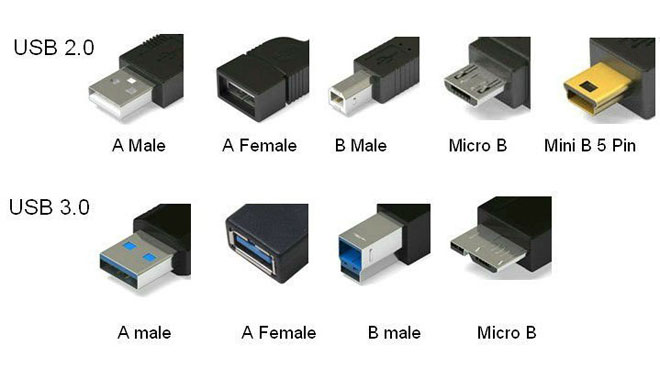
Although the serial bus is called a universal bus, there are 2 types. They perform different functions and provide compatibility with devices that have enhanced features.
Type A devices include active, powered devices (computer, host), type B - passive, pluggable equipment (printer, scanner). All sockets and plugs of the second generation and version 3.0 buses of type A are designed to work together. The connector of the 3.0 Type B bus jack is larger than needed for the 2.0 Type B connector, so a device with a 2.0 Type B Universal Bus connector is connected using only a USB 2.0 cable. External equipment with 3.0 Type B connectors is connected using both types of cables.
Classic Type B connectors are not suitable for connecting small-sized electronic equipment. Tablets, digital equipment, cell phones are connected using tiny Mini-USB connectors and their improved version, Micro-USB. These connectors have reduced dimensions of the plug and socket.
The latest modification of the USB connectors is the Type C. This design has the same connectors on both ends of the cable, has faster data transfer and more power.
USB 2.0 connector pinout types A and B
Classic connectors contain 4 types of contacts, in mini- and micro-formats - 5 contacts. The colors of the wires in the USB 2.0 cable:
- +5V (red VBUS), 5V voltage, 0.5A maximum current, designed for power;
- D- (white) Data-;
- D+ (green) Data+;
- GND (black), 0 V voltage, used for grounding.
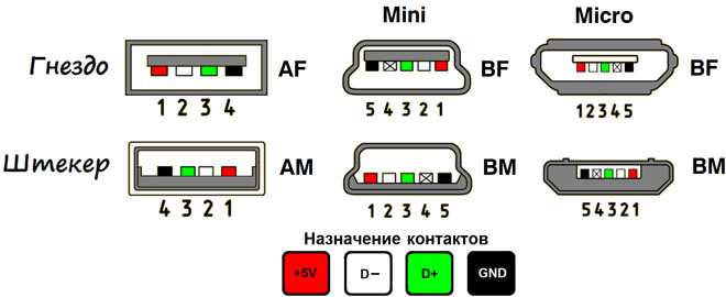
For the mini format: mini-USB and micro-USB:
- Red VBUS (+), voltage 5 V, amperage 0.5 A.
- White (-), D-.
- Green (+), D+.
- ID - for type A shorted to GND, to maintain the OTG function, and for type B not engaged.
- Black GND, 0V voltage, is used for grounding.
Most cables have a Shield wire, it has no insulation and is used as a shield. It is not labeled and is not assigned a number. The Universal Bus has 2 types of connector. They are marked M (male) and F (female). Connector M (dad) is called the plug and is inserted, the F connector (mother) is called a socket and is inserted into it.
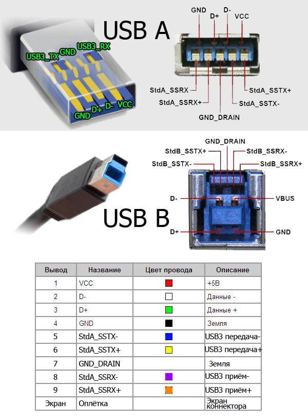
USB 3.0 Type A and B pinouts
The 3.0 bus has a 10 or 9 wire connection. The 9 pins are used if the Shield wire is missing. The pin assignment is done in a way that allows you to connect older devices.
USB 3.0 pinout:
- A - plug;
- B - socket;
- 1, 2, 3, 4 - The pins that coincide with the pin-out of the pins in the 2.0 specification have the same color scheme;
- 5, 6 contacts for data transmission via the protocol SUPER_SPEED, marked SS_TX- and SS_TX+, respectively;
- 7 - GND ground;
- 8, 9 - contact pads of the wires for receiving data according to the protocol SUPER_SPEED; contacts designation: SS_RX- and SS_RX+.
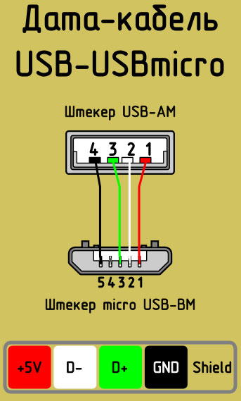
Micro-USB connector pinout
The Micro-USB cable has connectors with 5 pads. A separate color-coded insulated mounting wire is led to them. The shielding on top of the connector is specially chamfered to ensure that the connector fits snugly and accurately in the socket. The micro-USB pins are numbered from 1 to 5 and read from right to left.
The pin assignments of the micro- and mini-USB connectors are identical and are shown in the table below:
| Pin number | Designation | Color |
| 1 | VCC power supply 5V | red |
| 2 | data | white |
| 3 | data | green |
| 4 | ID function, for type A shorted to ground | |
| 5 | ground | black |
The shielding wire is not soldered to any of the pins.
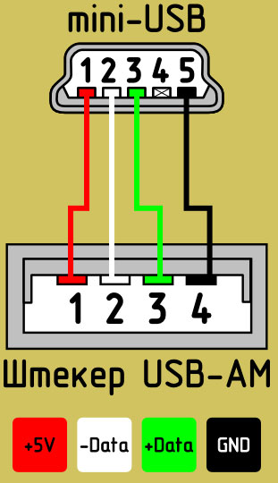
Mini-USB pinout
Mini-A and Mini-B connectors appeared on the market in 2000, used the USB 2.0 standard. To date, little used because of the emergence of more advanced modifications. They were replaced by micro-connectors and USB Type C models. The mini jacks use 4 shielded wires and an ID feature. 2 wires are used for power: +5V supply and GND ground. 2 wires for receiving and sending differential data signals, labeled D+ and D-pin. Data+ and Data- signals are transmitted over twisted pair. D+ and D- always work together, they are not separate simplex connections.
USB connectors use 2 types of cables:
- Shielded, 28 AWG twisted, 28 AWG power or 20 AWG non-twisted;
- Unshielded, 28 AWG twisted, 28 AWG or 20 AWG non-twisted power.
Cable length depends on power:
- 28 - 0,81 м;
- 26 - 1,31 м;
- 24 - 2,08 м;
- 22 - 3,33 м;
- 20 - 5 м.
Many manufacturers of digital equipment develop and equip their products with connectors of different configuration. This can cause difficulties with charging a cell phone or other devices.
Related articles: